Shocks and Hydraulic Lift
The standard kit comes with really nice shocks from QA1, but I opted for the Penske 8300 series upgrade. Even with the trade in value of the QA1s it's a $3,800 option (for another $4k I could have gone the 8700 series!). So why did I do it? According to Superlite, after tires it's the number one thing that can be done to improve the SL-Cs already superb handling. They are derived from technology Penske pioneered in their Indy car shocks and Superlite worked with them to optimize the valves for the SL-C's suspension. They feature remote reservoirs to better cool the shock fluid, 80-click rebound adjustment and 20-click compression adjustment.
Articles
Shock Absorbers
| Qty. | Part Number | Description | Unit Price | Ext. Price |
|---|---|---|---|---|
| 1 | n/a | Penske 8300 Series Upgrade | $3,800.00 | $3,800.00 |
| 2 | 0400.2530.0700 | Eibach 700 lbs./in., 4 in.Long, 2.5 in. ID Spring | $88.88 | $177.76 |
| 2 | 1877-2.50 | Hyperco 2.50 inch Zero-Rate Helper Spring | $34.99 | $69.98 |
| 2 | GC1160 | Genesis 2.5" Helper Spring Guide | $39.99 | $79.98 |
| 2 | 19410 | Joes Racing 1.25" Shock Reservoir Mount | $65.95 | $131.90 |
| Total | $4,259.62 |
Penske 8300 Series documentation:
The shocks are specifically ported for the SL-C as shown in the graphs below:


Rebound adjusters are the 'knob click' style with 80 clicks; mounted on top end of each shock with red anodized knob. Compression Adjusters mounted on the top of the remote reservoirs; hex adjuster 20 clicks
Front Shocks and Hydraulic Lift rams
Suboptimal shock and lift ram orientation
The front suspension was shipped in a suboptimal configuration. As can be seen in the picture to the right both the shock absorber body and the hydraulic lift ram are sitting on the lower control arm.
This is not the best orientation because:
It increases un-sprung weight (i.e., they are between the spring and the tire).
The shock absorber reservoir hose (visible) and the hydraulic ram hose (not installed yet, green tape covering the hole) will bounce up and down with the suspension.
To replace the spring, you need to remove the top bolt which requires you to remove one of the upper control arm's mounting points. Since spring rates are often changed when tuning the suspension, this is not something that you want to make more difficult than it needs to be.
The Penske logo is upside down;-)
Optimal shock and lift ram orientation
I called Penske to check if the orientation mattered and they said that it would work either way, but that most people mount the body to the chassis (i.e., opposite of what was shipped). Flipping the orientation of the shock absorber and the lift ram reduces un-sprung weight, keeps all of the hoses stationary and simplifies replacing the spring. I'm not aware of any downside to this orientation so it's a mystery to me as to why the factory ships the suspension the way that they do.
Even after reading all of the documentation, I wasn't sure how to remove the springs. I called Allan who has built 20+ cars and he indicated that he couldn't figure it either and had to call them -- so, I guess my man card is in tack;-) In any event, it's very simple. You insert something with a 0.25" diameter (I used a pin punch) into one of the holes in the spring retainer and rotate it counter clockwise.
When fully compressed the zero rate spring and helper spring guide are 3/4" tall. TBD, I need to copy blog post regarding their purpose here.

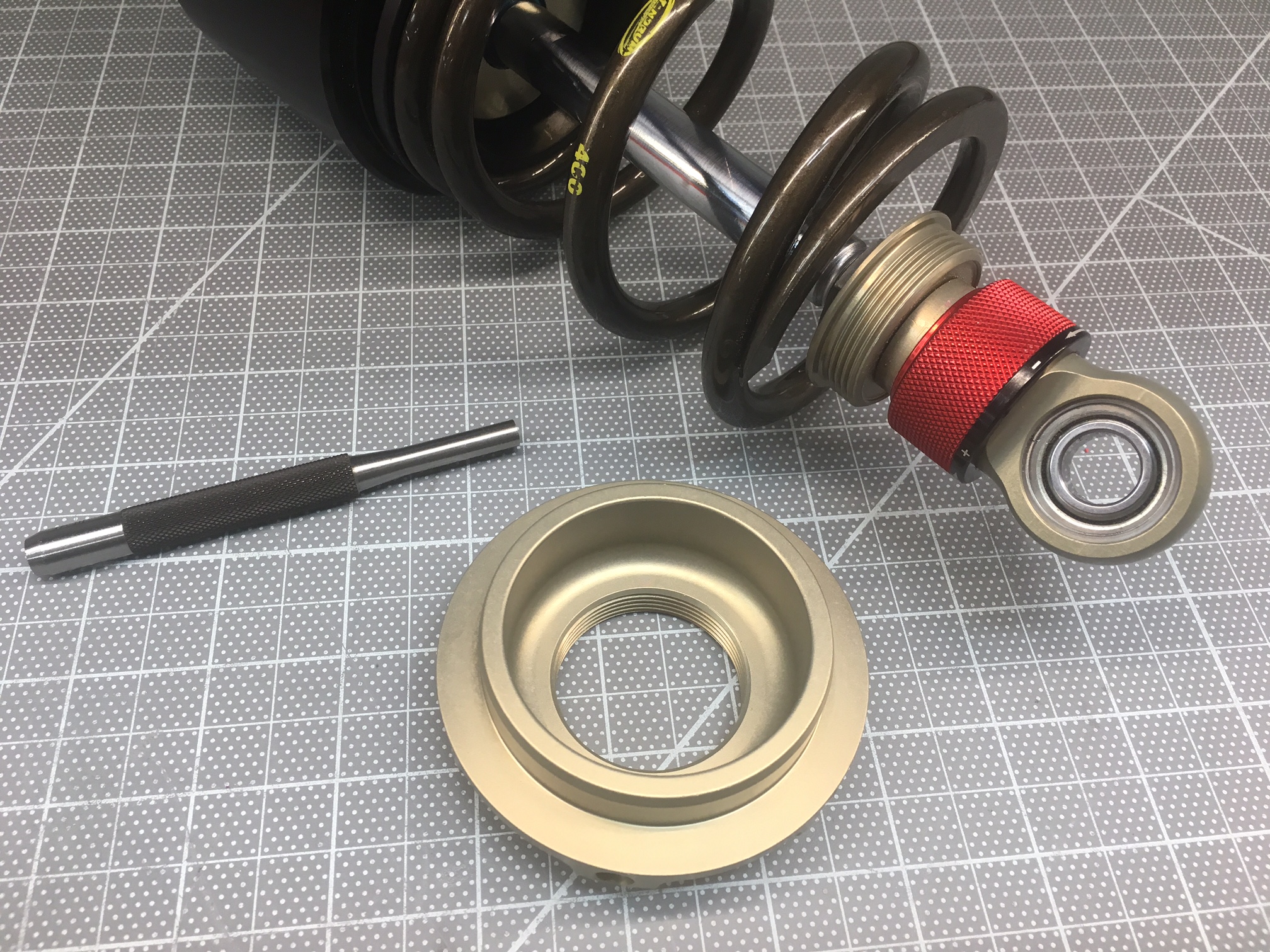
Penske offers the TL-76W tool for $22.50 which will work a little better than the punch. Steve at Penske also told me that when I reinstalled the spring retainer to "Tighten it until it was snug and then a little more -- probably less that 20 lb.-ft."
The lift ram can be oriented with the bleed port at the top or at the bottom. It is easier to bleed the air our of the system if the bleed port is at the top, so I went with that orientation.
Rear Shocks
TDB
Tweaking the Shocks - Bracket 2.0
The new bracket moved the mounting hole up 1.4" and out 0.25". The out was to clear to clear the upper mounting bolt for the suspension mounting bracket.
Stack height:
Zero rate spring: 0.535" (not about 1/4" as stated on the Pegasus site)
Zero rate spring plus the spring divider: 0.8"
Lift puck: 3-1/8"
700 Eibach 4" spring we estimate that the spring becomes coil bound at ~2.23 " of compression
With an initial body fitment we adjusted the threaded rod and heim joints to achieve "optimal" fitment. When measure on the 3D tool:
Max Compression: is the steering rack. That's because we moved the bracket up. Jacking the wheel until it hit the upper inner fender lip (which will eventually be trimmed) we had a max compression of 12.1"; we measure from the shaft o-ring to the shock cap was 1.2" -- we want to "fill" this space with a bump stop /spring
Shock body threads before I shipped them to Penske (front ride height at 4.5"):
Left: 5 threads
Right: 2.5 threads
Reservoir

Nitrogen Man Acessories
When I tried to reinstall the shocks I couldn't compress them at all, let alone the couple of inches required to fit them between the mounting points. This is because they are filled with about 150 psi of nitrogen (apparently the national championship SL-C ran 175 psi). There are three approaches to reinstalling the shocks:
Bleed the nitrogen. This makes it easy for a single person to do it. The downside is that you need to refill them with nitrogen.
Compress the shock in place. This requires careful use of a crowbar and two people. You might want to tape the top of the shock absorber to prevent it from being scratched by the crowbar.
Compress the shock on the bench. This requires you to compress it to the correct length and use wire to keep it compressed while you position it in place at which point you cut the wire.
I really didn't want to struggle getting it in place given that once it's in place you need to slide the bolt through a safety washer and two grade 8 washers on each side. So option one seemed best. The only downside with that approach means that you need to refill it with nitrogen which means that you need to buy more tools. The upside is that you get to buy more tools and you're set up to tune the pressure when you go to shake out the car.
The following are required to change the amount of nitrogen in the shocks:
Shock inflator
High-pressure regular
High-pressure hose
Nitrogen bottle
“Yeah sweetie, this is how a man accessorizes... a dress needs shoes and Penske shocks need a nitrogen setup LOL ”
The shock's oil reservoirs have a standard Schrader valve like you'd find on a car tire. However, you don't want to use standard tire inflation tools for two reasons: (1) the pressure is 150-200 psi which is 4-6 times higher and (2) there is a very small volume of nitrogen which means that the pressure is extremely sensitive to leakage when connecting or disconnecting to the valve. In fact, even specially designed shock inflators will reduce the pressure by 15-20 psi when checking the pressure. Note that the gauge will read the lowered pressure, not the pressure before you connected.
A shock inflator has a special high-pressure, no-loss chuck. It's used as follows:
Rotate the T-handle counterclockwise until it stops. This retracts the plunger.
Attach the chuck to Schrader valve. It uses a copper seal ring so it needs to be tightened a little with a wrench or it will leak. Be very careful not to damage or twist the Schrader valve. Ideally you would use a second wrench to hold the Schrader valve, but I couldn't get even my thin Snap-on box wrench to fit.
Slowly rotate the T-Handle clockwise to extend the plunger. If you hear any leaking, rotate the opposite way and repeat the above step. Keep rotating until the gauge shows the pressure.
At this point you can bleed the nitrogen from the Schrader valve on the inflator. Remember there is a very small volume of nitrogen so it's a thousand times more sensitive than bleeding pressure out of a tire. If you bleed all of the nitrogen out you'll want to re-inflate to at least 50 psi to keep pressure on the seals (I'll write that up later). When you've reached the desired pressure via inflation and/or deflation:
Rotate the T-handle counter clockwise until it stops. This retracts the plunger.
Loosen the chuck from the Schrader valve. The nitrogen that you hear is vacating the body of the inflator. Nothing leaks from the shock.


The Penske manual states that the gas pressure can range from 50-200 psi. Fran ran the race cars at 175psi.
Why vary nitrogen pressure? http://deltavee.net/2013/07/use-canister-nitrogen-pressure-to-tune-shocks/Rear Suspension
Hydraulic Lift Pump
The SL-C is extremely low and the nose and splitter project well forward of the front wheels. This results in a low approach angle which causes issues with steep driveways, railroad tracks, trailer ramps, speed bumps, etc. While this isn't an issue for a race car, it poses a serious challenge for a street/track car. To address this issue I opted for the hydraulic lift system from RAMLIFTpro. It includes a hydraulic pump and two hydraulic rams for the front suspension which raises the front edge of the car 3-1/2" or so within about five seconds.
The hydraulic lift system is from RAMLIFTpro. The Superlite instructions are here and the RAMLIFTPro instructions are here. The provided hose is Aeroquip Teflon Racing Hose -4 AN (part # FBC0400).
Some measurements from the test run with the prototype shock bracket installed:
Front Ride Height 4-1/2"
Rear Ride Height: 5"
Splitter to Ground @ Ride Height: 4-1/2"
Splitter to Ground @ Max Lift: 7"
When I removed the shocks I realized that there was no easy was to disconnect the hydraulic rams which means that oil gets everywhere and that I need to re-bleed the system. To solve these issues I purchased two -4 AN billet 6061-T6 Aluminium quick disconnects which are tested to 15,000 psi. They enable me to quickly disconnect the hydraulic rams without any fluid leaking.
I also changed some of the fittings that came with the pump for routing purposes. The instructions indicate that the pressure side should have a minimum working pressure of 100 bar (1,450 psi). The The 'A' and 'B' and 'R' ports are G1/4 BSPP (British Standard Parallel Pipe).
| Qty. | Part Number | Description | Unit Price | Ext. Price |
|---|---|---|---|---|
| 1 | TBD | RamLiftPro Hydraulic Lift Kit | $1,895.00 | $1,895.00 |
| 2 | 499404-BL | 90-Degree Swivel 1/8" NPT to -4 AN Adapter | - | - |
| 2 | AFQR101-4AN | Aeroflow -4 AN Quick Release Viton Seal | $83.60 | $167.20 |
| 1 | 3266-05 | 1/8" NPT Brake Bleeder Assembly (2 piece) | $4.89 | $4.89 |
| 2 | 3266-16 | 1/4"-28 Speed Bleeder Screw, 1" Overall Length | $9.69 | $19.38 |
| 1 | 9059-06-04 | 90° Elbow, 3/8" Male JIC x 1/4" Male BSPP Adj. - Steel | $9.66 | $9.66 |
| 1 | 9059-04-04 | 90° Elbow, 1/4" Male JIC x 1/4" Male BSPP Adj. - Steel | $9.66 | $9.66 |
| 1 | 16892 | Vibrant Performance -6 AN Fuel Cell Bulkhead Adapter Fitting | $9.99 | $9.99 |
| 2 | 3490-06-FOOT | 910 Aramid Braided PTFE Racing Hose, -6 AN (Per Foot) | $21.29 | $42.58 |
| 2 | 3481-06-STRAIGHT | Aluminum -6 AN Straight Hose End for 910 Aramid Braided PFTE Hose | $13.99 | $27.98 |
| 1 | n/a | 1/4" x 4" x 4" Right Angle Aluminum (6" Section) | - | - |
| 2 | n/a | 1/4"-20 x 2-3/4" Stainless Steel Socket Head Cap Screw | - | - |
| 2 | n/a | 1/4"-20 Nyloc | - | - |
| 4 | n/a | 1/4" Stainless Steel Washer | - | - |
| 4 | n/a | 10-24 x 3/4" Stainless Steel Socket Head Cap Screw | - | - |
| 4 | n/a | #10 Stainless Steel Nyloc | - | - |
| 8 | n/a | #10 Stainless Steel Washer | - | - |
| Total | $2,186.34 |
I decided to upgrade the hydraulic fluid reservoir from 3/8" push-on barbs to proper -6 AN fittings and hose. I spent a fair amount of time looking for reservoir with AN fittings to no avail. So I decided to modify the supplied one. I purchased a -6 AN Fuel Cell Bulkhead Adapter Fitting from Vibrant Performance which came with a nut and two PFTE washers. I removed the barb with a Dremel cut-off wheel, sanded the bottom flat and then carefully enlarged the hole. The nut was too big to fit so I had to grind it round and press fit it. Now I can sleep better knowing I have a proper AN fitting:-)
The reservoir bracket as supplied is on the left. The fitting nut and two PFTE washers are on the right. Note that the nut has already been ground round and that only one of the PTFE washers was used.

